2. blink_example_main.c 분석
/* Blink Example

   This example code is in the Public Domain (or CC0 licensed, at your option.)

   Unless required by applicable law or agreed to in writing, this
   software is distributed on an "AS IS" BASIS, WITHOUT WARRANTIES OR
   CONDITIONS OF ANY KIND, either express or implied.
*/
#include <stdio.h>
#include "freertos/FreeRTOS.h"
#include "freertos/task.h"
#include "driver/gpio.h"
#include "esp_log.h"
#include "led_strip.h"
#include "sdkconfig.h"

static const char *TAG = "example";

/* Use project configuration menu (idf.py menuconfig) to choose the GPIO to blink,
   or you can edit the following line and set a number here.
*/
#define BLINK_GPIO CONFIG_BLINK_GPIO

static uint8_t s_led_state = 0;

#ifdef CONFIG_BLINK_LED_RMT
static led_strip_t *pStrip_a;

static void blink_led(void)
{
    /* If the addressable LED is enabled */
    if (s_led_state) {
        /* Set the LED pixel using RGB from 0 (0%) to 255 (100%) for each color */
        pStrip_a->set_pixel(pStrip_a, 0, 16, 16, 16);
        /* Refresh the strip to send data */
        pStrip_a->refresh(pStrip_a, 100);
    } else {
        /* Set all LED off to clear all pixels */
        pStrip_a->clear(pStrip_a, 50);
    }
}

static void configure_led(void)
{
    ESP_LOGI(TAG, "Example configured to blink addressable LED!");
    /* LED strip initialization with the GPIO and pixels number*/
    pStrip_a = led_strip_init(CONFIG_BLINK_LED_RMT_CHANNEL, BLINK_GPIO, 1);
    /* Set all LED off to clear all pixels */
    pStrip_a->clear(pStrip_a, 50);
}

#elif CONFIG_BLINK_LED_GPIO

static void blink_led(void)
{
    /* Set the GPIO level according to the state (LOW or HIGH)*/
    gpio_set_level(BLINK_GPIO, s_led_state);
}

static void configure_led(void)
{
    ESP_LOGI(TAG, "Example configured to blink GPIO LED!");
    gpio_reset_pin(BLINK_GPIO);
    /* Set the GPIO as a push/pull output */
    gpio_set_direction(BLINK_GPIO, GPIO_MODE_OUTPUT);
}

#endif

void app_main(void)
{

    /* Configure the peripheral according to the LED type */
    configure_led();

    while (1) {
        ESP_LOGI(TAG, "Turning the LED %s!", s_led_state == true ? "ON" : "OFF");
        blink_led();
        /* Toggle the LED state */
        s_led_state = !s_led_state;
        vTaskDelay(CONFIG_BLINK_PERIOD / portTICK_PERIOD_MS);
    }
}
이는 esp-idf에 있던 예제인 blink_example_main.c이다.
먼저 이것을 빌드하여 플래쉬 해보았다.
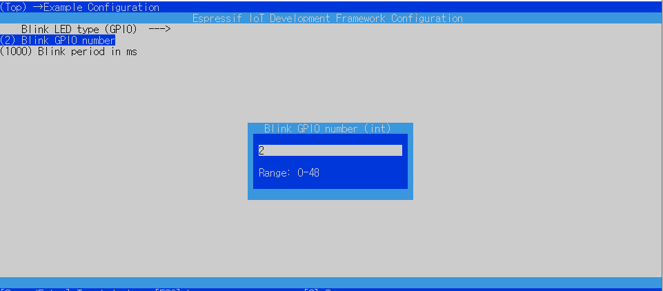
빌드하기 전에

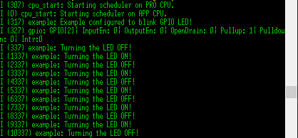
이는 실행 결과이다.
이제 코드를 분석해 보자.

여기서 line 26의 조건부 전처리기를 통해 line 52 부터 보면 되겠다.

CONFIG_BLINK_LED_GPIO는 조건부 전처리기를 사용하기 위한 플래그? 라고 생각한다.
CONFIG_BLINK_GPIO는 위에서 언급했듯 내장 LED의 GPIO 번호이고 이를 변경하면
blink_example_main.c에서도 적용된다.
메인의 line 57을 따라가면


gpio.c의 line 226의 첫번째 argument GPIO_IS_VALID_OUTPUT_GPIO는 위에서 결정한 CONFIG_BLINK_GPIO을 출력으로 사용 가능한가에 대한 검증하는 함수이다.
soc_caps.h에서 볼수 있듯 이는 24,28~31를 제외한 0~39 출력 가능한 gpio 번호라는 것이고, 34~는 입력 전용 gpio라는 것이다.
따라서 설정한 2라는 gpio는 출력 가능한 gpio이다.


gpio.c의 line 226의 두번째 argument "GPIO output gpio_num error"는
esp_check.h의 line 271이 참일 경우에 에러를 출력할때 나오는 문자열이다.
unlikely 라는 문법을 통해 대체로 이 에러 로그는 출력되지 않을 것을 뜻하며 위 문장에서도 마찬가지로 에러 로그가 출력되지 않는다.
gpio.c의 line 226의 세번째 argument는 0x102 이다. 만약 에러 로그가 출력된다면 어떤것이 오류였는지 알려주는 에러코드이다.
정리하면 gpio.c의 GPIO_CHECK()은 첫번째 인자로 출력가능한 gpio 번호인지 확인하고 아닐시에 두번째 인자를 출력 후 세번째 인자의 에러코드를 반환한다.


s_led_state는 현재 0으로 되어있고 이는 low 즉, off 라는 뜻이다.

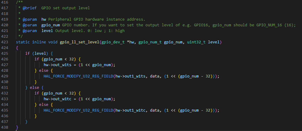
gpio_ll.h에서 level이 0이고 gpio_num은 2이므로 else문안의 if문이 실행된다.

out_w1tc에 값을 넣어 클리어 시킨다. 이는 gpio를 직접적으로 제어하는 문장인것 같다.
한마디로 gpio_set_level() 함수는 gpio를 출력가능한지 확인하고 확인됐다면 led를 켜주는 기능을 한다.

line 80과 같이 s_led_state를 1로 바꾸면 out_w1ts에 값을 넣어 셋을 시켜 키고 끔을 반복 할 수 있다.
이제 configure_led에 대해 알아보자.

먼저 "Example configured yto blink GPIO LED!"를 출력한다.
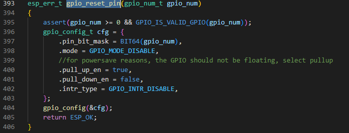


assert를 통해 gpio 번호와 가능한 번호인지 확인 후 gpio를 기본상태(gpio기능 선택, 풀업 활성화, 입력 및 출력 비활성화)로 재설정하며 '항상' ESP_OK을 반환한다.

사실 이 함수가 gpio_reset_pin과 output mode 로 설정하는 것 외에는 무엇이 다른지 잘 모르겠다.
찾아보니 이 함수는 only output, only input, input and output 과 같은 gpio의 방향을 설정하는 것이라고 한다...
결론은 blink_example_main.c는 gpio를 리셋하고 그 방향을 output으로 설정후
led에 불을 키고 끄는 프로그램인 것이다.